
An inertial measurement unit (IMUs) is an electronic component to measure the accelerations, angular velocity, and strength/direction of magnetic fields. IMUs are embedded in the inertial navigation systems. It utilizes the raw information from the IMUs to determine the position, angular/linear velocities, and attitude with respect to a global reference frame. Therefore, inertial navigation systems integrated with IMUs become the pivotal component for autonomous control and navigation in robotics. It has found many applications in the commercial and defence industry. Common applications include the determination of the direction and tracking motion in consumer electronics such as mobiles, virtual reality, and augmented reality. For industrial use, it can help the robots, such as drones, humanoids, vehicles, etc., for the logistic support. It includes the miniature microelectromechanical systems (MEMS) with three components (a) accelerometer, (b) gyroscope, and (c) magnetometer.
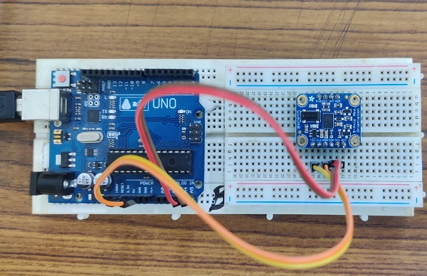
Task I: Connection diagram of Arduino UNO and MEMS Sensor.
Connect the Arduino pin A4 and A5 to the SDA and SCL of the sensor. Also, connect the 3.3 volts and GND pin from the board to the Vin pin and GND pin of the sensor. The complete circuitry is shown in Fig. 1.
Task II: Bias estimation and Calibration of the Sensor.
This is an important step because if the calibration of the sensor is not properly done, then the reading from the sensor will have bias and can result in inaccurate results. Likewise, a constant bias in acceleration can lead to a linear error and quadratic error in the velocity and distance estimation respectively. After calibration, there is noise present in measurement as shown in Fig. 2, which can be approximated by gaussian.
.png)
.png)
.png)
Task III: Estimation.
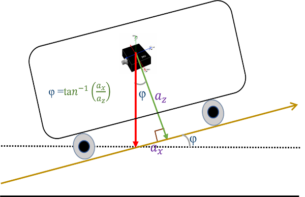
(a) Tilt estimation (using only accelerometer measurement):
A schematic diagram of the autonomous vehicle is shown in Fig. 3. Here, the vehicle is locomoted on the sloppy surface with a “φ” pitch angle. The mathematical expression for pitch evaluation is shown in Fig. 3. Likewise, the roll angle can also be evaluated by replacing the a_x by a_y. Fig. 4 presents the respective roll and pitch angle. However, it is also depicted from animations (right side) that both angles are highly sensitivities for vibrations (which are common events in nature). A low pass filter can be employed, which can partially solve the sensitivity problem.
(b) Tilt estimation (using only gyroscope measurement):
Roll and pitch angle can be evaluated using the gyroscope, an advantage of using gyro reading is that it is not susceptible to vibrations and provide a faster response as compared to the low-pass filter. Fig. 6. shows the animation for the tilt estimation based on the gyroscope readings. It depicts that the gyroscope is not impacted by vibrations, however, there will be drift in measurement in the long term. It is because of the accumulation of errors in measurements. A high pass filter can be used to solve this problem partially.
(c) Accurate and stable tilt estimation using the Complementary filter:
Since the pitch and roll estimation from the accelerometer measurement is susceptible to vibrations (Long term acceptance) whereas estimation from the gyroscope measurement leads to drifting (Short term acceptance). Therefore, the fusion of both approaches can lead to a more appropriate result as shown in Fig.7.
Overall comparison of all techniques for tilt measurement:
Fig. 8 shows the comparative analysis of all techniques for the tilt estimation. It shows that pitch and roll measured from the accelerometer and gyroscope separately provide the vibrations/overshoot and drifting. Then the low-pass filter shows the better utility regarding vibrations. Lastly, the complementary filter is presented which mostly address all issue of the above techniques. Whenever there is a sudden change in tilt after remaining constant at some position. There is a sudden overshoot as shown in the last part of an animation. Therefore, it is recommended to use these techniques according to the application. Additionally, it is recommended to use the higher-level filter such as Kalman filter, and Bayesian filter for a good estimation of these quantities.
(d) Estimation of Yaw:
It is noted from the above section that only pitch and roll are estimated. In order to estimate the yaw movement, magnetometer measurements are utilized as shown in Fig. 9. Since the Yaw angle helps the robots to navigate into the environment.
Future directions:
It is noted after the experiment that the orientation estimation is still affected by the noise, bias, and offset in the sensor. Therefore, it is recommended to use advanced filtering approaches such as the Kalman filter and Hidden Markov model.